Two UR10s with grippers
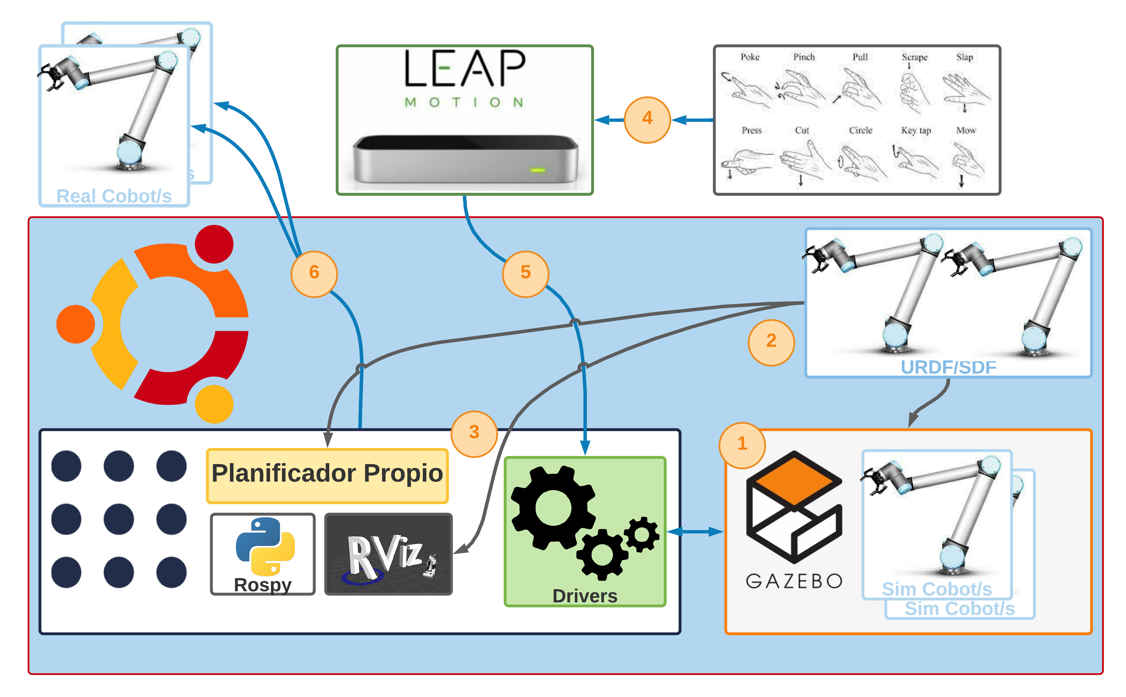
This time the solution for two robots is done in the same way as for one, changing the content of the files and adapting them to the simulation with two robots.
The phases you see in the diagram are for orientation. They can be executed in the order you want. The diagram has been divided into phases for the sake of order, so you know which element of the diagram is being worked on. In this case, it starts with Phase 1, followed by Phase 2, and finally ends with Phase 3. Note that there may be configurations in one phase that actually belong in another phase. If this is the case, it will be marked accordingly.
Prerequisite
- Successfully install the Basic System Configuration.
Index
Initial setup: setup for one robot
In this section, a replication of the configuration for a single robot is made, which serves as a basis and thus later explains the changes made to be able to control two robots.
 Contents of the file
Do not blindly copy and paste the contents of the files into this section. If you are explaining the configuration for one robot, the information is identical to that from the one_arm_no_moveit package, but you will need to adapt the contents to the new package, in this case two_arm_no_moveit.
There are two possibilities:
- If you created the solution for a one_arm_no_moveit robot, you can continue with what you implemented, but in the Modifications section you need to change two_arm_no_moveit to one_arm_no_moveit.
- If the solution for a one_arm_no_moveit robot has not yet been created, you can follow the steps presented in this section. Note, however, that the contents of the files at this stage of initial configuration are linked to the files of one_arm_no_moveit. Therefore, you must replace references to the one_arm_no_moveit package with two_arm_no_moveit when creating the copy.
If this information is not taken into account, the package will not compile correctly and the compiler itself will force you to choose between one of the previously suggested options.
Phase 1: Gazebo simulator configuration

Gazebo configuration
The first thing to do is to configure the Gazebo and the controllers so that it can properly simulate the cobot’s movements. The package two_arm_no_moveit_gazebo will be created, which will contain all the configurations for Gazebo, including the controllers.
Once the package is created, you will need to configure the controllers that are stored in the controller directory. The controllers are defined in files with the extension yaml. To define these controllers, you must give them a name and specify the type of controller, the dynamic joints you want to control, the constraints it has, the publishing ratio and other options.
The contents of the driver configuration files are shown below. All of these drivers generally follow the structure mentioned above. The definition of the controllers can be contained in a single file, the only important thing is that Gazebo loads them correctly. These controllers are briefly explained below:
-
File arm_controller_ur10.yaml: This file defines the controller for the UR10 cobot. It defines the controller name
arm_controller, the controller type elementcontrollers/JointTrajectoryControllerwhich contains the definition of the message type and the proper formatting of the information needed to communicate with the controller. Then there is thejointsfield that specifies whichjointsof the robot are part of the controller, all of thesejointsbeing dynamic. The other fields are left untouched, but care must be taken to name them consistently. -
File joint_state_controller.yaml: This file does not actually define a controller as such, its function is that of an interface that translates the
jointinformation coming from the real cobot and converts it intoJointStatetype messages that are later published. It is essential for correct operation both in simulation and with the real robot. It is part of the package ROS ros_control.
 Create solution directory
cd ~/MultiCobot-UR10-Gripper/src/multirobot
mkdir two_arm_no_moveit
 Launch of
 Gazebo
Starting Gazebo
Currently it is not possible to run Gazebo with the robot from the created directory of the project. The first step is to start Gazebo with the UR10 robot.
To bring some order to the structure of the project to be implemented, the use of the different tools and their files will be separated if possible. This allows a better understanding of the structure and facilitates later debugging.
Therefore, instead of a directory, a package will be created that contains everything related to Gazebo:
cd ~/MultiCobot-UR10-Gripper/src/multirobot/two_arm_no_moveit
catkin_create_pkg two_arm_no_moveit_gazebo rospy
In the directory created for Gazebo it copies the directory ur_gazebo, the folders controller and launch.
cd ~/MultiCobot-UR10-Gripper/src/multirobot/two_arm_no_moveit/two_arm_no_moveit_gazebo
cp -r ~/MultiCobot-UR10-Gripper/src/universal_robot/ur_gazebo/controller .
cp -r ~/MultiCobot-UR10-Gripper/src/universal_robot/ur_gazebo/launch .
It compiles:
cd ~/MultiCobot-UR10-Gripper
catkin_make
With this you can now start Gazebo from the project directory.
roslaunch two_arm_no_moveit_gazebo ur10.launch

Gazebo’s world setup
Now we proceed to create the world with the robot and an environment where it can perform simple tasks. This project focuses on the tasks that the robot can perform, so it is not necessary for the world to be very detailed.
For this purpose, you must first create the world directory where the created worlds will be stored:
cd ~/MultiCobot-UR10-Gripper/src/multirobot/two_arm_no_moveit/two_arm_no_moveit_gazebo
mkdir world
The file world from another repository is used, which provides a very simple scenario that allows later debugging of the robot’s tasks.
cd ~/MultiCobot-UR10-Gripper/src/multirobot/two_arm_no_moveit/two_arm_no_moveit_gazebo
git clone https://github.com/Infinity8sailor/multiple_arm_setup.git
cp -r multiple_arm_setup/multiple_ur_description/models/ .
cp -r multiple_arm_setup/multiple_ur_description/world/ .
sudo rm -r mutiple_arm_setup
To add the world with the robot in Gazebo you have to change the file ur10.launch in the directory launch:
cd ~/MultiCobot-UR10-Gripper/src/multirobot/two_arm_no_moveit/two_arm_no_moveit_gazebo/launch
nano ur10.launch
And include the world in launch by adding the world argument and replacing the value of default in the world_name argument:
 <arg name="world" default="$(find two_arm_no_moveit_gazebo)/world/multiarm_bot.world" />

  <!-- startup simulated world -->
  <include file="$(find gazebo_ros)/launch/empty_world.launch">
    <arg name="world_name" default="$(arg world)"/>
    <arg name="paused" value="$(arg paused)"/>
    <arg name="gui" value="$(arg gui)"/>
  </include>
We proceed to launch Gazebo with the new world:
roslaunch two_arm_no_moveit_gazebo ur10.launch
When launching it, it shows two errors:
Error [parser.cc:581] Unable to find uri[model://dropbox]
This error can only be fixed if the model is created from scratch, since it is not provided by Gazebo or has been removed. Therefore, the object dropbox in the multiarm_bot.world file is commented:
<!--include>
       <pose frame=''>0.5 0.0 0.3 0 0 0</pose>
       <uri>model://dropbox</uri>
       <name>DropBox</name>
</include-->
[ERROR] [1639740881.902412642, 0.057000000]: GazeboRosControlPlugin missing <legacyModeNS> while using DefaultRobotHWSim, defaults to true.
This setting assumes you have an old package with an old implementation of DefaultRobotHWSim, where the robotNamespace is disregarded and absolute paths are used instead.
If you do not want to fix this issue in an old package just set <legacyModeNS> to true.
To fix this error, we make the change in the file universal_robot/ur_descriptiom/urdf/common.gazebo.xacro and add *
<plugin name="ros_control" filename="libgazebo_ros_control.so">
      <!--robotNamespace>/</robotNamespace-->
      <!--robotSimType>gazebo_ros_control/DefaultRobotHWSim</robotSimType-->
      <legacyModeNS>true</legacyModeNS>
</plugin>
 Installing
 Gazebo 9 [Optional]
There could be a warning that is a problem if ignored when simulating the arm behavior in the future.
[ WARN] [1639745803.729749460, 0.061000000]: The default_robot_hw_sim plugin is using the Joint::SetPosition method without preserving the link velocity.
[ WARN] [1639745803.729772883, 0.061000000]: As a result, gravity will not be simulated correctly for your model.
[ WARN] [1639745803.729786659, 0.061000000]: Please set gazebo_pid parameters, switch to the VelocityJointInterface or EffortJointInterface, or upgrade to Gazebo 9.
To this end, it was decided to install Gazebo 9 in the ROS Kinetic Kame environment.
sudo apt-get remove ros-kinetic-desktop-full
sudo apt-get remove ros-kinetic-gazebo*
sudo apt-get upgrade

sudo apt-get install ros-kinetic-ros-base

sudo sh -c 'echo "deb http://packages.osrfoundation.org/gazebo/ubuntu-stable `lsb_release -cs` main" > /etc/apt/sources.list.d/gazebo-stable.list'
cat /etc/apt/sources.list.d/gazebo-stable.list
wget https://packages.osrfoundation.org/gazebo.key -O - | sudo apt-key add -
sudo apt-get update

sudo apt-get install ros-kinetic-gazebo9-ros-pkgs ros-kinetic-gazebo9-ros-control ros-kinetic-gazebo9*

sudo apt-get install ros-kinetic-catkin

sudo apt-get install rviz

sudo apt-get install ros-kinetic-controller-manager ros-kinetic-joint-state-controller ros-kinetic-joint-trajectory-controller ros-kinetic-rqt ros-kinetic-rqt-controller-manager ros-kinetic-rqt-joint-trajectory-controller ros-kinetic-ros-control ros-kinetic-rqt-gui

sudo apt-get install ros-kinetic-rqt-plot ros-kinetic-rqt-graph ros-kinetic-rqt-rviz ros-kinetic-rqt-tf-tree

sudo apt-get install ros-kinetic-gazebo9-ros ros-kinetic-kdl-conversions ros-kinetic-kdl-parser ros-kinetic-forward-command-controller ros-kinetic-tf-conversions ros-kinetic-xacro ros-kinetic-joint-state-publisher ros-kinetic-robot-state-publisher

sudo apt-get install ros-kinetic-ros-control ros-kinetic-ros-controllers
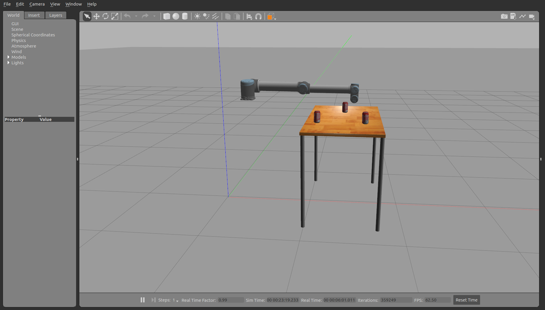
The result after installing Gazebo 9 looks similar to the following.
Phase 2: URDF configuration
 Description of the URDF file
The URDF (United Robotics Description Format) file models the cobot in XML format, which is used by the various applications that ROS requires, but mainly to perform a simulation of the modeled robot.
The file is built in the form of a tree in which there are three main tags: <robot>, <link> and <joint>. For clarity, you can take the arm of the human body as a reference. If you want to model the arm of a person, the tag <robot> would represent the arm as a whole. This arm consists of several bones (humerus, ulna and radius) represented by tag <link> and a joint connecting these bones (elbow) represented by tag <joint>.
As with bones, additional information about size, geometry, inertia, orientation, etc. can be added to these tags. Finally, the modeling of a robot can be connected to another model to form a more complex model that can be represented by adding the hand to the arm, where the wrist is a joint that connects the two. Note that <joint> tags connect ` ` tags via a parent-child relationship.
This creates a representation of the robot components:
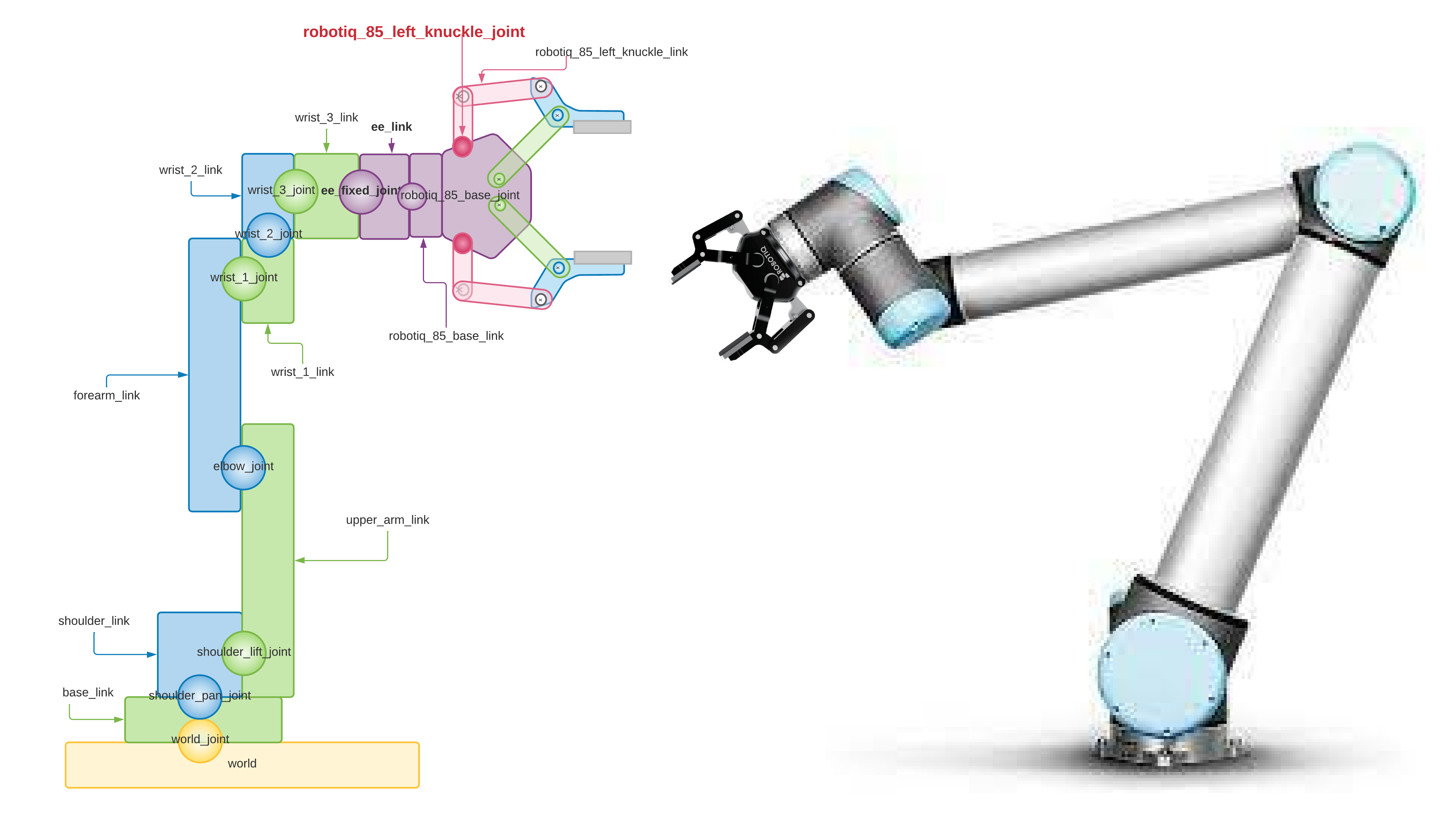
The image shows the contents of the URDF file that models the robot next to the gripper. You can see how the component of the UR10 robot arm is connected to the link world which represents the world (yellow color) and the base of the UR10 arm base_link (green color) which is directly above it, also the joint world_joint is the yellow ball located between both links. In the same way, the component of the gripper robotiq_85_gripper is connected to the arm of the UR10 (ur10_robot). The ball representing the joint robotiq_85_base_joint connecting both components (purple color) connects the link robotiq_85_base_link of the gripper with the link ee_link of the UR10 arm.

 Adding the robotiq_2f_85_gripper to the UR10 robot [Not possible, problems with
 Gazebo]
To add the gripper correctly, you must first understand how it works. Installation instructions can be found here.
Take a look at the following image to understand how the gripper control works:

You can see 2 nodes, one acting as a client and the other as a server. The server is responsible for sending jobs to the gripper and feedback to the client and the client sends jobs to the server.
If we compare the configuration of the controller with that of the UR10, we notice that the concept is different because there is no yaml file that loads the necessary information to control the gripper. Instead, it is the server that creates the topics /command_robotiq_action and /robotiq_controller/follow_joint_trajectory, both of which are of type action.
miguel@Omen:~$ rostopic list
/clicked_point
/command_robotiq_action/cancel
/command_robotiq_action/feedback
/command_robotiq_action/goal
/command_robotiq_action/result
/command_robotiq_action/status
/initialpose
/joint_states
/move_base_simple/goal
/robotiq_controller/follow_joint_trajectory/cancel
/robotiq_controller/follow_joint_trajectory/feedback
/robotiq_controller/follow_joint_trajectory/goal
/robotiq_controller/follow_joint_trajectory/result
/robotiq_controller/follow_joint_trajectory/status
/rosout
/rosout_agg
/tf
/tf_static
Knowing this, to control the gripper, there is an example in the file robotiq_2f_action_client_example.py and can work with a simulated gripper or the real gripper. Bearing this in mind, when adding the gripper to the UR10 robot, the yaml file that would load the driver controller is not necessary, but the node that will act as the server must be launched correctly and if you look at the server code and from the client, special care must be taken with the configuration of the topics and namespaces.
The file that uploads the UR10 robot is universal_robot/ur_description/launch/ur10_upload.launch, therefore, we will copy what is necessary from the ur_description package and modify it to add the gripper to the robot and also modify the file ur10.launch which loads the URDF of the ur_gazebo package:
cd ~/MultiCobot-UR10-Gripper/src/multirobot/two_arm_no_moveit
catkin_create_pkg two_arm_no_moveit_description rospy
cd two_arm_no_moveit_description
mkdir launch
cp ~/MultiCobot-UR10-Gripper/src/universal_robot/ur_description/launch/ur10_upload.launch launch/
mkdir urdf
cp ~/MultiCobot-UR10-Gripper/src/universal_robot/ur_description/urdf/ur10_robot.urdf.xacro udrf/
cp ~/MultiCobot-UR10-Gripper/src/universal_robot/ur_description/urdf/ur10_joint_limited_robot.urdf.xacro udrf/
The exact reason why it is not possible to simulate the gripper correctly is not known, because Gazebo shows the following error:
[ERROR] [1640030309.858708751, 1040.204000000]: This robot has a joint named "finger_joint" which is not in the gazebo model.
[FATAL] [1640030309.858805517, 1040.204000000]: Could not initialize robot simulation interface
It does not work in the simulation with Gazebo, but it does in the Rosviz tool. This indicates that the ROS package for the gripper works correctly, but the simulated robot configuration in Gazebo (real robot) is not correct. Surely they should be treated as independent elements that physically work as a whole, which is not the case with this simulation in Gazebo.
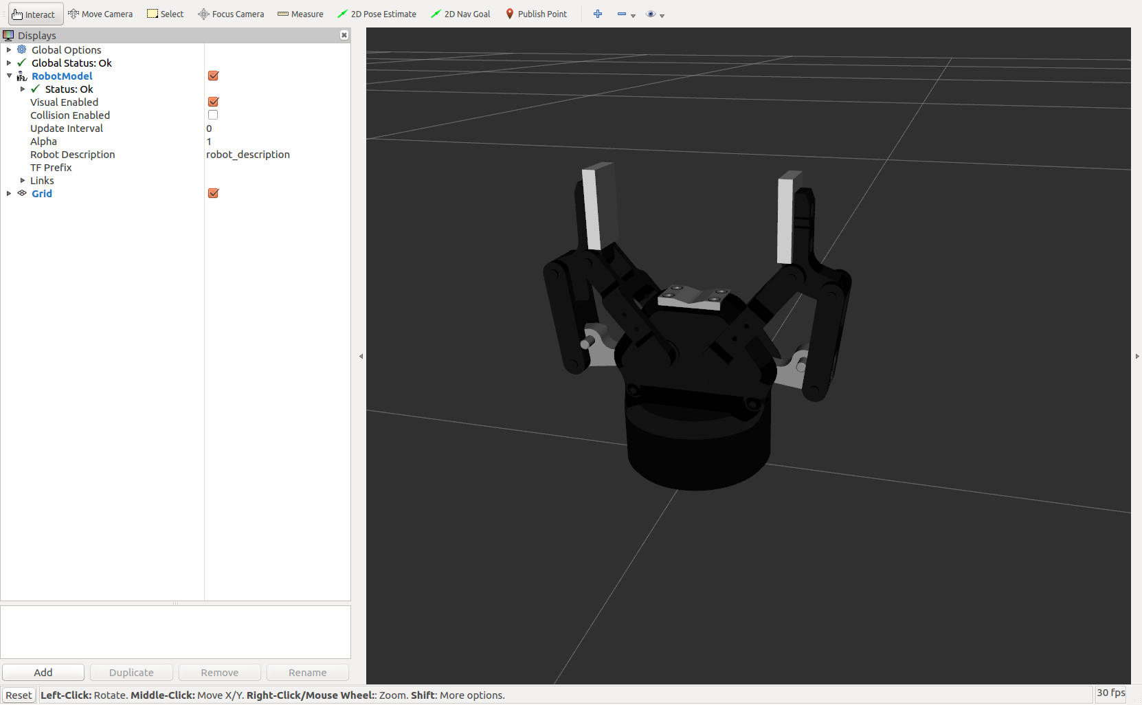
Since the gripper in the real robot is an independent element of the robot arm, this repository may be necessary, but for the simulations another repository compatible with the Gazebo simulator is used.
 Adding the robotiq_85_gripper to the UR10 robot
In the process of adding the gripper to the UR10 robot. There are no clear instructions on how to do this properly. So let us first look at how the package is built to get an idea of how to adapt it to the project in question.
LICENSE             robotiq_85_description  robotiq_85_moveit_config  si_utils
README.md           robotiq_85_driver       robotiq_85_msgs
robotiq_85_bringup  robotiq_85_gripper      robotiq_85_simulation
At first glance, the packages we are interested in are robotiq_85_description, robotiq_85_bringup and robotiq_85_simulation, the rest are resources for use with MoveIt! or scripts used later to control the gripper in the simulation.
In this sense, the gripper is built into the UR10 robot.
For example, take the file robotiq_85_gripper/robotiq_85_description/urdf/robotiq_85_gripper.xacro and insert the gripper into the robot by changing the files:
- multirobot/two_arm_no_moveit/two_arm_no_moveit_description/urdf/ur10_robot.urdf.xacro
- multirobot/two_arm_no_moveit/two_arm_no_moveit_description/urdf/ur10_joint_limited_robot.urdf.xacro.
And with that you have the gripper on the UR10 robot. You can see the gripper on the picture.
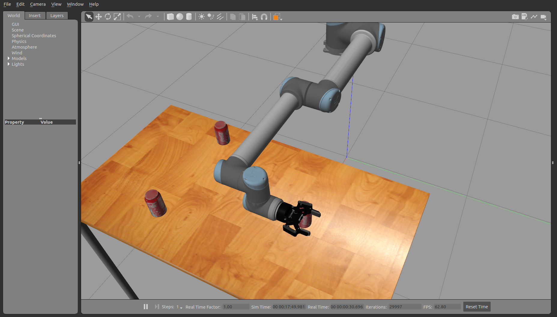
 Gripper Controller Aggregation (Gazebo, phase 1)
Now the controllers are missing to send orders to the gripper. You can check this by looking in the list of active topics to see that there is no controller for the gripper:
miguel@Omen:~$ rostopic list
/arm_controller/command
/arm_controller/follow_joint_trajectory/cancel
/arm_controller/follow_joint_trajectory/feedback
/arm_controller/follow_joint_trajectory/goal
/arm_controller/follow_joint_trajectory/result
/arm_controller/follow_joint_trajectory/status
/arm_controller/state
/calibrated
/clock
/gazebo/link_states
/gazebo/model_states
/gazebo/parameter_descriptions
/gazebo/parameter_updates
/gazebo/performance_metrics
/gazebo/set_link_state
/gazebo/set_model_state
/gazebo_gui/parameter_descriptions
/gazebo_gui/parameter_updates
/joint_group_position_controller/command
/joint_states
/rosout
/rosout_agg
/tf
/tf_static
You can see that the UR10 robot controllers are loaded (/arm_controller), but there is no topic for the gripper controller. To change this you need to add them as follows and load them correctly in Gazebo.
The files with the gripper control information are located in the directories robotiq_85_gripper/robotiq_85_simulation/robotiq_85_gazebo/controller and robotiq_85_gripper/robotiq_85_simulation/robotiq_85_gazebo/launch, which points to the controller and launch directories of the two_arm_no_moveit_gazebo.
Finally, the following changes were made:
cd ~/MultiCobot-UR10-Gripper/src/multirobot/two_arm_no_moveit/two_arm_no_moveit_gazebo/controller
cp ~/MultiCobot-UR10-Gripper/src/robotiq_85_gripper/robotiq_85_simulation/robotiq_85_gazebo/controller/gripper_controller_robotiq.yaml .
And at the end of the file multirobot/two_arm_no_moveit/two_arm_no_moveit_gazebo/launch/ur10.launch added the gripper controller:
<!-- robotiq_85_gripper controller -->
  <rosparam file="$(find two_arm_no_moveit_gazebo)/controller/gripper_controller_robotiq.yaml" command="load"/>
  <node name="gripper_controller_spawner" pkg="controller_manager" type="spawner" args="gripper" />
Restart Gazebo (roslaunch two_arm_no_moveit_gazebo ur10.launch) and with the command rostopic list you can see that the gripper controllers are displayed correctly (/gripper):
/arm_controller/command
/arm_controller/follow_joint_trajectory/cancel
/arm_controller/follow_joint_trajectory/feedback
/arm_controller/follow_joint_trajectory/goal
/arm_controller/follow_joint_trajectory/result
/arm_controller/follow_joint_trajectory/status
/arm_controller/state
/calibrated
/clock
/gazebo/link_states
/gazebo/model_states
/gazebo/parameter_descriptions
/gazebo/parameter_updates
/gazebo/performance_metrics
/gazebo/set_link_state
/gazebo/set_model_state
/gazebo_gui/parameter_descriptions
/gazebo_gui/parameter_updates
/gripper/command
/gripper/follow_joint_trajectory/cancel
/gripper/follow_joint_trajectory/feedback
/gripper/follow_joint_trajectory/goal
/gripper/follow_joint_trajectory/result
/gripper/follow_joint_trajectory/status
/gripper/state
/joint_group_position_controller/command
/joint_states
/rosout
/rosout_agg
/tf
/tf_static
Phase 3: Implementation of a custom motion planner that performs a pick & place
 Creating the motion planner and the helper Nodes
The ROS policy of splitting tasks into nodes is followed whenever possible to facilitate future reuse.

In the figure you can see the schema for the structure of the implemented planner architecture. You can see two sections: Gazebo (the nodes in red color and the topics in orange color) and the planner (the nodes in blue color and the topics in green color), divided in this way to facilitate the explanation.
The Gazebo group of nodes and topics did not need to be touched and their existence was exploited to obtain the necessary information to allow the planner to perform its task. This group communicates with the planning group through three topics /tf that contain information about robot transformations, and the topics /gripper/command and /arm_controller/command that receive the necessary information to execute movements in the robot.
Since these nodes and topics are known to the Gazebo group, the solution for the planner is to communicate with them to get the needed information. The node ur10_robot_pose receives the transformation information and sends the position of the end-effector to the node robot_manipulator, which performs two main functions: The first is controlling the gripper and the second is planning the trajectory of the effector. The cmd_gripper_value_pub and cmd_ik_trajectory_pub nodes receive commands from the robot_manipulator node and send them directly to the topics of the controllers of Gazebo (/gripper/command and /arm_controller/command).
Having explained how the solution works in general, we now explain what each node does in detail:
-
ur10_robot_pose: This script creates a node that posts only the position of the end-effector with a given frequency (10 Hz) via the tf library of ROS, i.e. it obtains the position of the end-effector from the information of the topic
/tfpublished in the topic/robot_pose. The position of the end-effector is obtained from the difference between the positions of/base_linkand/ee_link(the link that connects to the gripper). This node is not really necessary, therobot_manipulatornode could do this itself, albeit redundantly, but very useful for debugging and understanding how the motion planner works. -
pub_gripper_cmd: The script creates a node that only receives commands from topic
/pub_gripper_controland forwards them to topic gripper controller/gripper/command. Although the functionality is simple, this node allows changes to the value sent to the controller at any time because it does not perform a check to see if the move was executed correctly, which is a desired behavior. And if it does not receive an order, it continues to publish the previous order and keeps the value of the gripper. If it receives a new order, it immediately discards the previous value so that changes can be made while a move is executing. -
pub_ik_trajectory: Works the same way as described for the
cmd_gripper_value_pubnode, this script instantiates thecmd_ik_trajectory_pubnode. It receives commands from the topic/pub_ik_trajectoryto which it subscribes and transmits them to the arm controller topic/arm_controller/command. Also, changes can be made while executing a trajectory, allowing sudden changes in direction without having to wait until the previously specified position is reached. -
robot_manipulator: This script instantiates the
robot_manipulatornode and determines the current position of the end-effector of the topic/robot_pose. This information is necessary to determine the values of each joint needed to achieve the desired Cartesian position. Once the value that the joints must have is determined, they are published via the topic/pub_ik_trajectory. We had to implement a script that works as a library. This library consists of several functions that perform the necessary calculations to obtain the forward kinematics and the inverse kinematics. In the case of the gripper, since only the value of a joint needs to be controlled, no computation is required; the desired value is simply passed to the function. In the implementation, it is necessary to take into account the type of messages that the controllers must receive in order to set them correctly, otherwise they will not perform any movements or they will perform undesirable movements. This solution can lead to problems since singularities can occur because divisions by zero can occur when calculating the equations, especially when two joints are aligned. To avoid this, the robot’s workspace was simply constrained in this case.
 robot_pose_publisher script
We will implement a node that publishes the position of the end effector ee_link at any time, using the library tf.
Since this is a tool and not a script that gives commands to the robot, this script will be provided in the Gazebo directory.
cd ~/MultiCobot-UR10-Gripper/src/multirobot/two_arm_no_moveit/two_arm_no_moveit_gazebo/scripts
touch ur10_robot_pose.py
chmod +x ur10_robot_pose.py
- View the contents of the ur10_robot_pose.py file.
This node calculates the position of the ee_link relative to the position of the base_link using the tf library and publishes it in the topic \robot_pose. This allows you to quickly determine the current position of the gripper.
- To automatically launch the file, add the following to the multirobot/two_arm_no_moveit/two_arm_no_moveit_gazebo/launch/controller_utils.launch file.
  <!-- get the robot position [Own Script]-->
  <node name="ur10_robot_pose" pkg="two_arm_no_moveit_gazebo" type="ur10_robot_pose.py" respawn="true" />
 pub_gripper_cmd script
It enables the control of the gripper. For this purpose, a node is created that listens to a topic (/pub_gripper_control) from which it receives the value it sends to the controller via the topic /gripper/command.
This node is a support node, it is located next to the Gazebo scripts, near the driver files:
cd ~/MultiCobot-UR10-Gripper/src/multirobot/two_arm_no_moveit/two_arm_no_moveit_gazebo/scripts
touch pub_gripper_cmd.py
chmod +x pub_gripper_cmd.py
-
See the contents of the file pub_gripper_cmd.py.
-
To launch the file automatically, add the following to the multirobot/two_arm_no_moveit/two_arm_no_moveit_gazebo/launch/controller_utils.launch file.
<!-- send the gripper commands [Own Script]-->
  <node name="cmd_gripper_value_pub" pkg="two_arm_no_moveit_gazebo" type="pub_gripper_cmd.py" respawn="true" />
 pub_ik_trajectory script
A node is implemented that receives commands via the topic /pub_ik_trajectory and sends them repeatedly to the robot controllers. The position it has to move to is changed when it receives new commands.
Since this is a tool and not a script that gives commands to the robot, this script is implemented in the Gazebo directory, just like in the previous section.
cd ~/MultiCobot-UR10-Gripper/src/multirobot/two_arm_no_moveit/two_arm_no_moveit_gazebo/scripts
touch pub_ik_trajectory.py
chmod +x pub_ik_trajectory.py
-
View the contents of the pub_ik_trajectory.py file.
-
To automatically launch the file, add the following to the multirobot/two_arm_no_moveit/two_arm_no_moveit_gazebo/launch/controller_utils.launch file.
  <!-- send the arms commands [Own Script]-->
  <node name="cmd_ik_trajectory_pub" pkg="two_arm_no_moveit_gazebo" type="pub_ik_trajectory.py" respawn="true" />
 robot_manipulator script
We will implement a node that receives the information received from the robot_pose_publisher node and sends the trajectories to the pub_ik_trajectory node.
To get the values of the joints based on the Cartesian position you want to move to, you need to implement the Inverse Kinematics and Forward Kinematics functions. These functions were taken from The Construct and adapted.
For this:
cd ~/MultiCobot-UR10-Gripper/src/multirobot/two_arm_no_moveit/two_arm_no_moveit_manipulator/scripts
touch kinematics_utils.py
chmod +x kinematics_utils.py
- Displays the contents of the kinematics_utils.py library.
Once the library is implemented, we proceed to develop the node that sends commands to the robot to perform the desired tasks, in this case pick & place, where the cobot picks a cube from the table and places it in a basket until there are no more cubes on the table.
cd ~/MultiCobot-UR10-Gripper/src/multirobot/two_arm_no_moveit/two_arm_no_moveit_manipulator/scripts
touch robot_manipulator.py
chmod +x robot_manipulator.py
It contains a set of functions to send the final trajectories correctly and get the values of the joints in the position of the robot.
- See the contents of the library robot_manipulator.py.
The robot has problems depending on the coordinates passed, since singularities can occur if the robot is blocked by constraints on the mathematical domain (for example: if theta2 = acos(1), the value is undefined and generates an error or divisions for zero).
To avoid this, a workspace can be defined where these singularities do not occur.
Implementation of tests
 Testing in
 Gazebo
A test was created where the robot grabs three wooden cubes and sends them into a container.
The file with the manipulator code to perform the test: multirobot/two_arm_no_moveit/two_arm_no_moveit_manipulator/scripts/robot_manipulator.py
Commands to launch the test:
- Terminal 1:
cd ~/MultiCobot-UR10-Gripper/
source devel/setup.bash
roslaunch two_arm_no_moveit_gazebo ur10_joint_limited.launch
- Terminal 2:
cd ~/MultiCobot-UR10-Gripper/
source devel/setup.bash
rosrun two_arm_no_moveit_manipulator robot_manipulator.py
 Problems with pick & place testing
At the beginning of the tests it turned out that in the simulation in Gazebo it is not possible to pick up the objects on the table.
This is due to the absence of the Gazebo plugin gazebo_grasp, which is included in the package gazebo-pkgs, previously installed as a resource.
 Gazebo Grasp Plugin
We now perform the necessary steps to load the plugin that will allow the robot to interact with the objects in the simulation.
First, we need the file gzplugin_grasp_fix.urdf.xacro (you can get it from the repository of Jennifer Buehler). It could be stored in the universal robots package, but since it is a modification for this project, it was decided to move it to the multirobot /two_arm_no_moveit/two_arm_no_moveit_description/urdf directory.
cd ~/MultiCobot-UR10-Gripper/src/multirobot/two_arm_no_moveit/two_arm_no_moveit_description/urdf
touch gzplugin_grasp_fix.urdf.xacro
- See the contents of the file gzplugin_grasp_fix.urdf.xacro .
Once you have the Gazebo plugin, you need to add it to the robot arm. The code to increase friction has also been added to the gripper to help it grab objects in the simulation.
nano ~/MultiCobot-UR10-Gripper/src/multirobot/two_arm_no_moveit/two_arm_no_moveit_description/urdf/ur10_robot.urdf.xacro
Add the plugin at the end:
  <xacro:include filename="$(find two_arm_no_moveit_description)/urdf/gzplugin_grasp_fix.urdf.xacro"/>

  <xacro:gzplugin_grasp_fix prefix=""/>
- See the contents of the file ur10_robot.urdf.xacro .
In the same way we edit the gripper file (robotiq_85_gripper/robotiq_85_description/urdf/robotiq_85_gripper.urdf.xacro):
nano ~/MultiCobot-UR10-Gripper/src/robotiq_85_gripper/robotiq_85_description/urdf/robotiq_85_gripper.urdf.xacro
- View the contents of the robotiq_85_gripper.urdf.xacro file.
This is all you need to configure the plugin correctly. If there are multiple robots, the plugin must be assigned correctly for each gripper, otherwise these grippers will not be able to grab objects during the simulation.
Modifications: Multirobot system consisting of two robots

Before starting the changes to add two robots to the system, the picture shows how the nodes and the communication between Gazebo, the controllers and the scheduler are set up.
This is a replication of what was previously developed in Phase 3 for a single robot. Therefore, note that changes are made to the Gazebo controllers and their scripts that enable communication between them and the scheduler, as well as changes to the robot modeling (URDF) and the script that runs the Pick & Place task.
Be careful with the scaling in this solution, the name of the joints must be unique, this is due to the configuration of the robot model. Since it is not in a namespace that automatically generates unique names for the joints, you will have to make the changes manually, which will also affect the names of the topics and cause them to be duplicated. You will also need to modify the scripts to publish and subscribe to the correct topics.
This does not mean that the system itself is not scalable, because it is easy to give the scripts an argument that can be used as a prefix, which would automatically generate unique names from the launch files, just like a namespace.
Phase 1: `Gazebo` simulator configuration

Gazebo configuration
In this configuration, you need to redefine the files that configure the Gazebo controllers. Basically, you need to duplicate them and add the prefix ur10_1 and ur10_2 to the name of the joints, both for the clamp and for the arm of UR10.
Similarly, duplicate nodes suitable for communicating with the cobot controllers in Gazebo should be added to the controller_utils.launch file, as well as nodes that retrieve the current positions of each cobot from topic /tf.
 Changes that must be made to simulate two robots in
 Gazebo.
First, we need to define the namespace for each robot, the group name under which we will group the configurations for each of the robots.
We will start with the controllers:
- File ur10_1_arm_controller.yaml
cd ~/MultiCobot-UR10-Gripper/src/multirobot/two_arm_no_moveit/two_arm_no_moveit_gazebo/controllers
mv arm_controller_ur10.yaml ur10_1_arm_controller.yaml
View the contents of the ur10_1_arm_controller.yaml file with the changes made.
You can see that the ur10_1_ prefix was simply added. This then allows you to distinguish which connections the commands should be sent to, which also requires a change to the URDF file.
Now we change the rest of the files and add the second set of controls for the second robot, which get the prefix ur10_2_.
- file ur10_1_gripper_controller_robotiq.yaml.
cd ~/MultiCobot-UR10-Gripper/src/multirobot/two_arm_no_moveit/two_arm_no_moveit_gazebo/controllers
mv gripper_controller_robotiq.yaml ur10_1_gripper_controller_robotiq.yaml
View the contents of the ur10_1_gripper_controller_robotiq.yaml file with the changes made.
- File ur10_2_arm_controller.yaml
cd ~/MultiCobot-UR10-Gripper/src/multirobot/two_arm_no_moveit/two_arm_no_moveit_gazebo/controllers
cp ur10_1_arm_controller.yaml ur10_2_arm_controller.yaml
View the contents of the ur10_2_arm_controller.yaml file with the changes made.
- File ur10_2_gripper_controller_robotiq.yaml
cd ~/MultiCobot-UR10-Gripper/src/multirobot/two_arm_no_moveit/two_arm_no_moveit_gazebo/controllers
mv ur10_1_gripper_controller_robotiq.yaml ur10_2_gripper_controller_robotiq.yaml
View the contents of the ur10_2_gripper_controller_robotiq.yaml file with the changes made.
 Modification of the
 Gazebo launch file
Now we need to change the launch file to launch the controllers of the two robots in Gazebo.
cd ~/MultiCobot-UR10-Gripper/src/multirobot/two_arm_no_moveit/two_arm_no_moveit_gazebo/launch
nano ur10.launch
View the contents of the ur10.launch file with the changes made.
cd ~/MultiCobot-UR10-Gripper/<src/multirobot/two_arm_no_moveit/two_arm_no_moveit_gazebo/launch
nano ur10_joint_limited.launch
View the contents of the ur10_joint_limited.launch file with the changes made.
You still need to change the file that launches the previously created scripts, as well as these files, as they have been corrected to correctly match the namespace:
-
multirobot/two_arm_no_moveit/two_arm_no_moveit_gazebo/launch/controller_utils.launch
-
multirobot/two_arm_no_moveit/two_arm_no_moveit_gazebo/scripts/ur10_1_pub_gripper_cmd.py
-
multirobot/two_arm_no_moveit/two_arm_no_moveit_gazebo/scripts/ur10_1_pub_ik_trajectory.py
-
multirobot/two_arm_no_moveit/two_arm_no_moveit_gazebo/scripts/ur10_1_robot_pose.py
-
multirobot/two_arm_no_moveit/two_arm_no_moveit_gazebo/scripts/ur10_2_pub_gripper_cmd.py
-
multirobot/two_arm_no_moveit/two_arm_no_moveit_gazebo/scripts/ur10_2_pub_ik_trajectory.py
-
multirobot/two_arm_no_moveit/two_arm_no_moveit_gazebo/scripts/ur10_2_robot_pose.py
Phase 2: URDF configuration
 File description URDF
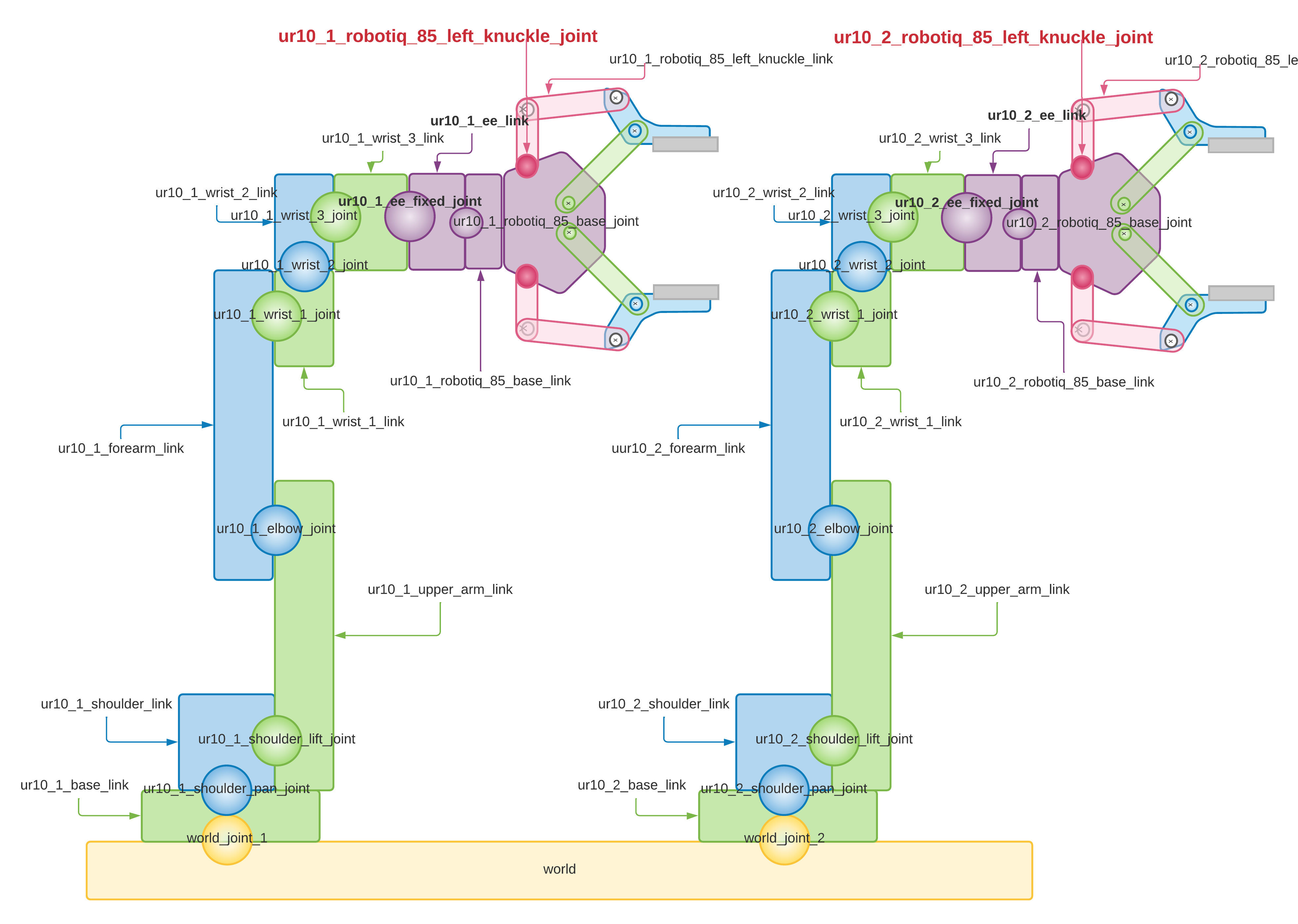
It is similar to the Phase 1 of the first configuration, except that this time there are two UR10 cobots, not just one. In the URDF file, you can see how the components of the ur10_robot arms are connected to the world link. This can be seen in the image that shows the world (yellow colour) and the bases of the UR10 arms ur10_1_base_link and ur10_2_base_link (yellow colour. green) that are directly above it. Also the joints ur10_1_world_joint and ur10_2_world_joint are the yellow spheres located between the two links. In the same way, the components of the robotiq_85_gripper gripper are connected to the arms of the UR10s (ur10_robot) that you can see in the picture where the balls represent the joints ur10_1_robotiq_85_base_joint and ur10_2_robotiq_85_base_joint, that connect both components (they are purple) that connect ur10_1_robotiq_85_base_link and ur10_2_robotiq_85_base_link of the brackets to the ur10_1_ee link and ur10_2_ee_link of the arms of the UR10.
 Description of the directory configuration
You have to change the files .urdf, ur10_joint_limited_robot.urdf.xacro and ur10_robot.urdf.xacro:
- Modify the file multirobot/two_arm_no_moveit/two_arm_no_moveit_description/urdf/ur10_joint_limited_robot.urdf.xacro with:
 [...]

  <!-- arm -->
  <xacro:ur10_robot prefix="ur10_1_" joint_limited="true"
    shoulder_pan_lower_limit="${-pi}" shoulder_pan_upper_limit="${pi}"
    shoulder_lift_lower_limit="${-pi}" shoulder_lift_upper_limit="${pi}"
    elbow_joint_lower_limit="${-pi}" elbow_joint_upper_limit="${pi}"
    wrist_1_lower_limit="${-pi}" wrist_1_upper_limit="${pi}"
    wrist_2_lower_limit="${-pi}" wrist_2_upper_limit="${pi}"
    wrist_3_lower_limit="${-pi}" wrist_3_upper_limit="${pi}"
    transmission_hw_interface="$(arg transmission_hw_interface)"
/>

  <link name="world" />

  <joint name="ur10_1_world_joint" type="fixed">
    <parent link="world" />
    <child link = "ur10_1_base_link" />
    <origin xyz="0.6 -0.6 1.1" rpy="0.0 0.0 0.0" />
  </joint>

  <!-- gripper -->
  <xacro:robotiq_85_gripper prefix="ur10_1_" parent="ur10_1_ee_link" >
      <origin xyz="0 0 0" rpy="0 0 0"/>
  </xacro:robotiq_85_gripper>

  <xacro:gzplugin_grasp_fix prefix="ur10_1_" prefix2="ur10_2_"/>
  <!--xacro:gzplugin_grasp_fix prefix="ur10_1_"/-->

  <!-- arm -->
  <xacro:ur10_robot prefix="ur10_2_" joint_limited="true"
    shoulder_pan_lower_limit="${-pi}" shoulder_pan_upper_limit="${pi}"
    shoulder_lift_lower_limit="${-pi}" shoulder_lift_upper_limit="${pi}"
    elbow_joint_lower_limit="${-pi}" elbow_joint_upper_limit="${pi}"
    wrist_1_lower_limit="${-pi}" wrist_1_upper_limit="${pi}"
    wrist_2_lower_limit="${-pi}" wrist_2_upper_limit="${pi}"
    wrist_3_lower_limit="${-pi}" wrist_3_upper_limit="${pi}"
    transmission_hw_interface="$(arg transmission_hw_interface)" />

  <joint name="ur10_2_world_joint" type="fixed">
    <parent link="world" />
    <child link = "ur10_2_base_link" />
    <origin xyz="0.6 1.38 1.1" rpy="0.0 0.0 0.0" />
  </joint>

  <!-- gripper -->
  <xacro:robotiq_85_gripper prefix="ur10_2_" parent="ur10_2_ee_link" >
      <origin xyz="0 0 0" rpy="0 0 0"/>
  </xacro:robotiq_85_gripper>
- Modify the file multirobot/two_arm_no_moveit/two_arm_no_moveit_description/urdf/ur10_robot.urdf.xacro with:
[...]
  <!-- arm -->
  <xacro:ur10_robot prefix="ur10_1_" joint_limited="false"
    transmission_hw_interface="$(arg transmission_hw_interface)"
  />

  <link name="world" />

  <joint name="ur10_1_world_joint" type="fixed">
    <parent link="world" />
    <child link = "ur10_1_base_link" />
    <origin xyz="0.6 -0.6 1.1" rpy="0.0 0.0 0.0" />
  </joint>

  <!-- gripper -->
  <xacro:robotiq_85_gripper prefix="ur10_1_" parent="ur10_1_ee_link" >
      <origin xyz="0 0 0" rpy="0 0 0"/>
  </xacro:robotiq_85_gripper>

  <xacro:gzplugin_grasp_fix prefix="ur10_1_" prefix2="ur10_2_"/>

  <!-- arm -->
  <xacro:ur10_robot prefix="ur10_2_" joint_limited="false"
    transmission_hw_interface="$(arg transmission_hw_interface)"
  />

  <joint name="ur10_2_world_joint" type="fixed">
    <parent link="world" />
    <child link = "ur10_2_base_link" />
    <origin xyz="0.6 1.38 1.1" rpy="0.0 0.0 0.0" />
  </joint>

  <!-- gripper -->
  <xacro:robotiq_85_gripper prefix="ur10_2_" parent="ur10_2_ee_link" >
      <origin xyz="0 0 0" rpy="0 0 0"/>
  </xacro:robotiq_85_gripper>
Phase 3: Implementation of a custom motion planner that performs a pick & place
 Creating the Scheduler and the Helper Nodes
The scheduler was previously developed in Phase 1 of this modification section for a two-robot multirobot system, where the nodes that are part of the scheduler were implemented.
This section now focuses on implementing the scripts that use the developed library to perform the direct kinematics to control the robot arms.
For the Pick & Place task, two scripts are implemented that are started in different terminals so that they send commands to each robot simultaneously.
 Modification of the Pick & Place
In the directory two_arm_no_moveit_manipulator the following files are modified:
-
multirobot/two_arm_no_moveit/two_arm_no_moveit_manipulator/ur10_1_robot_manipulator.py.
-
multirobot/two_arm_no_moveit/two_arm_no_moveit_manipulator/ur10_2_robot_manipulator.py.
The Gazebo plugin needs to be fixed so it can grab objects with both grippers:
And finally, customise the world file to run the simulations in a suitable environment:
Execution of tests
 Launch simulation tests
3 terminals are needed:
- Terminal 1:
roslaunch two_arm_no_moveit_gazebo ur10_joint_limited.launch - Terminal 2:
rosrun two_arm_no_moveit_manipulator ur10_1_robot_manipulator.py - Terminal 3:
rosrun two_arm_no_moveit_manipulator ur10_2_robot_manipulator.py
 Final result information
-
Visual result in
Gazebo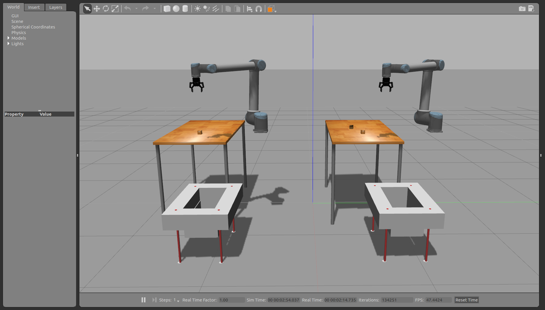
-
Scheme of the nodes and topics of the system

-
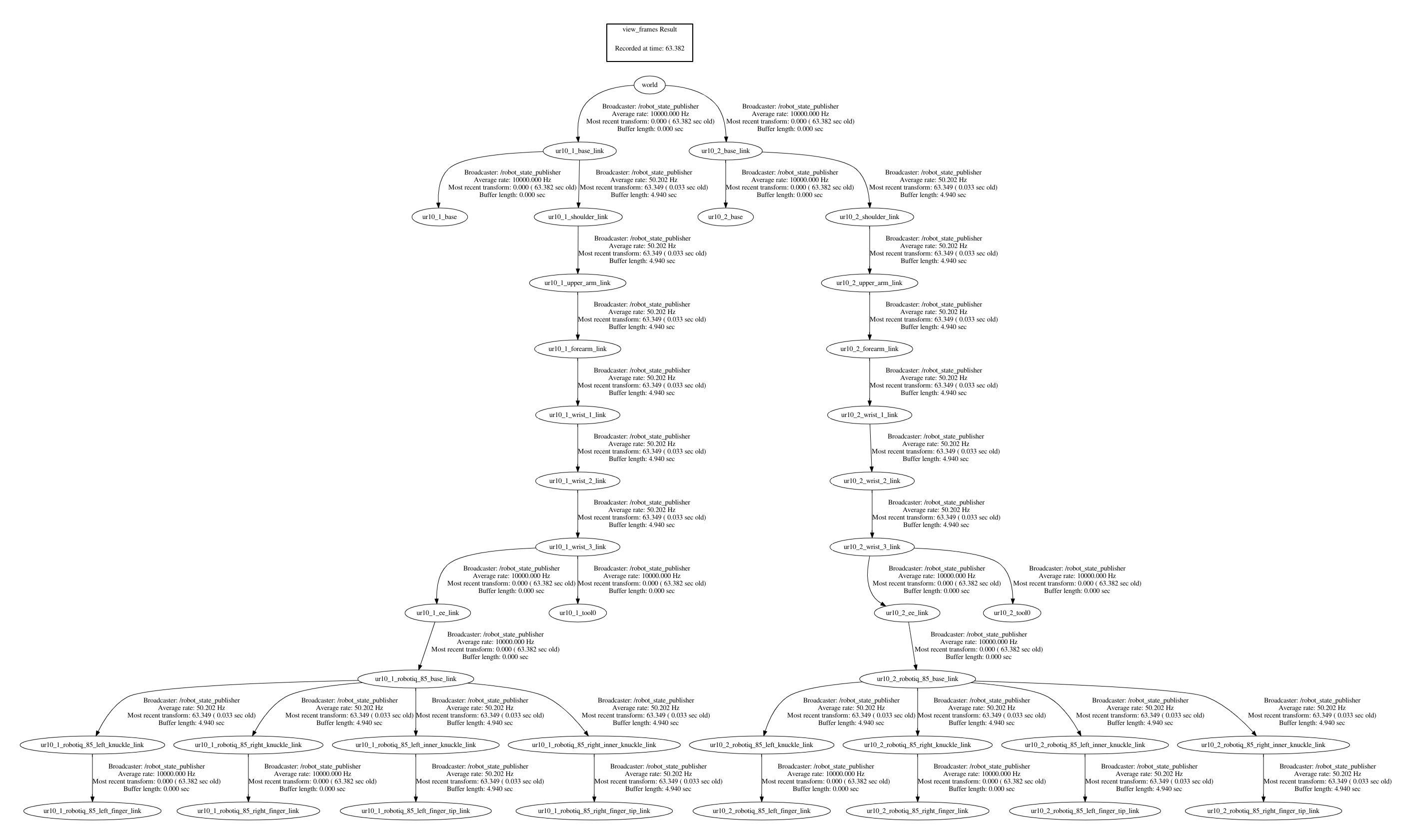
Tree of transformations of the robot model
